
When an injection mold designer is approached to build a mold for plastic components, there are many critical design considerations for different types of injection molds, regardless of the industry. Plastic injection molding is the manufacturing process of choice for engineers seeking plastic parts for their products ranging from toys and combs to high-precision molded parts required in several different industries. Some of these industries include:
- Consumer Electronics
- Automotive
- Aerospace
- Government / Military
Engineers are seeking quality-minded injection mold building companies with modern equipment, CAD (Computer Aided Design) Capabilities, Mold Flow Analysis, Prototyping Services, and experience building a variety of tools for use in different molding situations. Mold makers and engineers alike are aware that in order to obtain a quality part, you must begin with a quality tool. The term tool and mold are used interchangeably to describe the steel plates with cavities to form a plastic injection molded part. The accurate designing of those cavities in the steel is the key to obtaining a part molded to customer specifications.
Part Design
One of the first things that a mold designer considers is the part design. This includes carefully evaluating the location of all critical dimensions which may include for example, a thin wall that could succumb to underfill, or a dimension that is critical to keeping an assembly line moving. Part tolerances, including all required quality acceptable data provided by the customer, will let the designer know which areas must meet strict tolerances sometimes as exact as +/- .001 of an inch. The injection mold builder must also know the surface finish of the part, the texture required, and any restrictions on parting line or knit lines for proper gating.
Molding Environment
Another very important mold design consideration is the molding environment that the tool will run in. A designer must know the specific press the mold will run in and properties of that press such as whether it has a horizontal or vertical clamping system. A vertical press will require shuttle molds often with multiple B halves, and is typically used in insert molding, or over-molding which is molding plastic around an object typically made of either plastic or steel. The object, or insert, is placed into the cavity prior to the plastic being injected into the mold, so that plastic is molded around the insert. Sometimes to put a rubber like finish around a steel object, for example. This process is typically performed with the mold opening and closing vertically, for ease in loading and unloading of inserts. A typical injection molding press has a horizontal clamping system, and parts fall into a bin below when the mold opens and ejects them. Molding plastic around an insert vertically reduces the emphasis of gravity on the process.
The location of water fittings for cooling systems, electrical connectors and wiring preferences is also an important consideration for the mold to fit and work properly in the press. Care must be taken so that all of the mold plumbing does not interfere with the tie-bars or the clamping system of the press. The size of the locating ring and the radius of the sprue is important for proper fitting, and volume determination.
The molding environment also includes the tonnage of the press, the clamping pressure that can be powered by either hydraulics or electric, barrel capacity which must exceed the required volume, and the mounting system, all of which are equally important factors when designing a mold. The most common type of mounting systems is toe-clamping, although others would be spigot, magnetic, or even custom mounting plates. The platen layout must be large enough for the mold to fit but also to pass through the tie-bars for loading or unloading of the mold. The tie bars are what hold the platens in place, holding the mold in place, and also house the ejection system and allows the mold to open and close.
Cam Action
In addition to all of these considerations, if the mold is designed with cam action, extra care must be taken to ensure that there is room for all movements required. Cam action refers to a sliding plate of the steel surfaces with the shape that would create an undercut exterior feature, such as a hole in a part, for example. If the surface required to mold the exterior feature runs perpendicular to the mold opening and closing motions, sliding cams must be used or the part would not eject out of the cavity. A cam device pulls the side-action mold surfaces out of the way allowing the parts to be ejected from the mold.
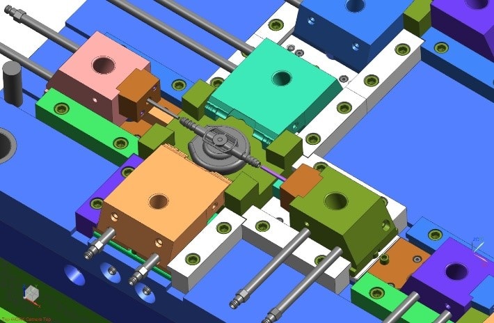 Here is an example of cam action; the sliding plates have barrel like rods attached that move in during molding to create holes in the part, then slide out when finished for proper ejection.
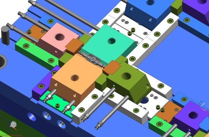 This photo shows cams in a closed position, while molding the hollow section of the part.
Lifters and Ejection System
Any required lifters must be apparent prior to mold building. A lifter is a mechanism in the ejector system, that has to be angled in order for other features to mold the geometry of the part. A lifter is part of the ejector plate system, and is activated by ejection, as opposed to cam action or a slider plate which is activated by the opening and closing of the mold.
The ejection system alone has several considerations. The ejection pattern and stroke of the press must correspond to the design of the mold. The location of ejector pins is crucial for proper ejection without damage to the finished product, this is where lifters are used when necessary. Where the parts fall when they eject is also important. If there is a robot reaching in and grabbing the runner, or the parts, the ejection system must accommodate any automated auxiliary equipment. In some cases, a two stage ejection system might be necessary if the parts are going to free fall into a tub or bin below upon ejection.
Cooling System
Most molds require a water cooling system which consists of water lines running through the mold to properly cool the molded product. Mold designers must be careful when designing the plumbing for the tool so that it does not interfere with press restrictions on the tie-bar or clamping system.
Customer Standards
Each injection mold manufacturer will have a set of standards for their equipment which will detail the size of their presses, any mold base construction requirements, type of steel and hardness needed, all electrical and cooling requirements, the ejection pattern and any CAD or part design data. The volume of the product to be produced is helpful information, along with customer expectations regarding part finish and functionality. The molder will also already know the type of resin the product will be molded in as the part designer has already dictated the specific resin to be used.
Thermoplastic Resin
There are several different types of thermoplastic resins, the most common type of polymer used in injection molding. Different resins have varying properties that will affect the outcome of the finished product. Some material will shrink more than others, or at different rates. This is extremely important when cutting dimensions in the steel mold, shrinkage must always be taken into consideration. Each resin also has specific properties for cooling and ejecting. Molding with fiberglass or glass filled nylons can affect the flow of material, and the wear on the tool.
Mold flow analysis is computer aided simulation software to clearly show how the material will flow and fill the mold. This is a valuable tool that gives mold builders a tremendous advantage. Predicting where critical fill issues lie, and adjusting for tight tolerance areas before problems arise, is crucial to meeting specifications in a short time frame. This simulation is especially helpful for designing molds for parts with tight tolerances, complex geometrical shapes where material flow is less predictable, and revealing weaknesses in part design. Mold flow analysis is also helpful to optimize the proper location for gating or for multiple gate locations, to improve the quality of the product and most importantly to avoid costly mistakes and improve lead times.
Most knowledge of how a material will flow, however, comes from experience. An experienced molder will have used the same resin in the past and have familiarity with how it melts, flows, molds and ejects. Experienced mold makers will have built tools that use the same resin, and know how to carve out the cavities on each side (A & B Plate), to meet dimensions. It is difficult to be conservative as the part must mold from the A & B halves coming together, a builder cannot be conservative on only one side. Building a mold is precision work, one that requires several considerations including the material that will flow through it to create a molded part.
Summary
In summary, as you can see there are numerous design considerations for different molds. While there is no substitution for experience, mold builders today must utilize the new technology and computer aided simulations to produce the most appropriate tool for the project. A skilled mold builder will know just which type of tool will best suit your project needs by taking into consideration the part design and manufacturability of the geometrical tolerances involved, the environment the mold will run in and the overall functionality of the part required as derived by customer specifications.
Contact Michiana Global Mold today for full service mold building of any type of tool from prototyping only a few hundred parts to millions of parts for high volume precision components. We have the engineering technology, and the experience to build a quality mold, which is the key to quality parts.