
Michiana Global Mold has years of experience determining the correct type of mold to build for your parts requirements. Our engineering group considers all aspects of the mold build including part design and volume required, the molding environment and mounting systems, specific mold action activity including cams, lifters and custom ejection systems, resin used and specific customer requirements. After careful consideration of your project requirements, our team can recommend the proper mold for the job. Please see following a description of the most common types of mold bases.
Types of Molds
The part or project requirement will dictate the type of mold to be built. Michiana Global Mold has experience constructing different molds to meet different demands. The most common types of molds built are prototypes, MUD (Master Unit Die) molds, typical full size molds that have a cold-runner system, hot-runner molds, hot-to-cold molds, shuttle systems, and three plate tools. Let’s take a look at each one and the criteria used in determining which mold will be needed.
Prototype Molds
A prototype mold is the only tool that could be constructed with aluminum as it is intended to be used for testing purposes only, not supporting any production requirements. A designer may want to construct a prototype for a brand new design if they are not familiar with the dimensions and want to see how the part will function in real life scenarios. This is a good way have an actual part to use for testing purposes if still evaluating the best dimensional fit for the project.
MUD Units
A MUD (Master Unit Die) Unit is a universal frame to fit in the press that allows an insert mold to slide in and out quickly rather than clamping a full size mold into the press. The MUD frame allows for quick changeovers, and reduces labor costs and machine down time. The ability to set up a mold without removing the frame also improves delivery especially in a just-in-time environment, which in turn improves profitability. This is an economical option for customers because one steel frame could house several different insert cavities, as opposed to constructing a full size standard mold for each product, thus saving potentially thousands of dollars.
Standard Mold
The typical standard mold consists of two halves, an A & B side, that come together to mold the part inside the cavity, or cavities. This is used in a horizontal clamping environment, with a cold runner system. When molten plastic resin is injected into the mold at the gate location, it must flow through a channel built in the mold to reach the cavities where the part will be molded. This channel is called the cold runner system, or simply just the runner or sprue, which are used interchangeably to describe the hardened plastic that ejects from the channel when the parts eject. The size of the runner is of great importance to the molder and the customer, as all material costs money and must be quoted into the project. Less waste is realized when the size of the runner can be reduced. Some molders can grind up the runner and reuse the regrind material, while some runners are simply scrap as the regrind cannot be reused. This is a great consideration when deciding between a cold runner mold, and a hot runner mold.
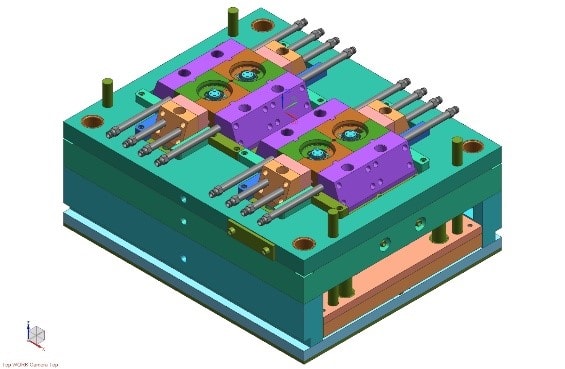
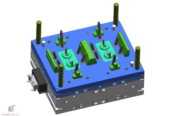
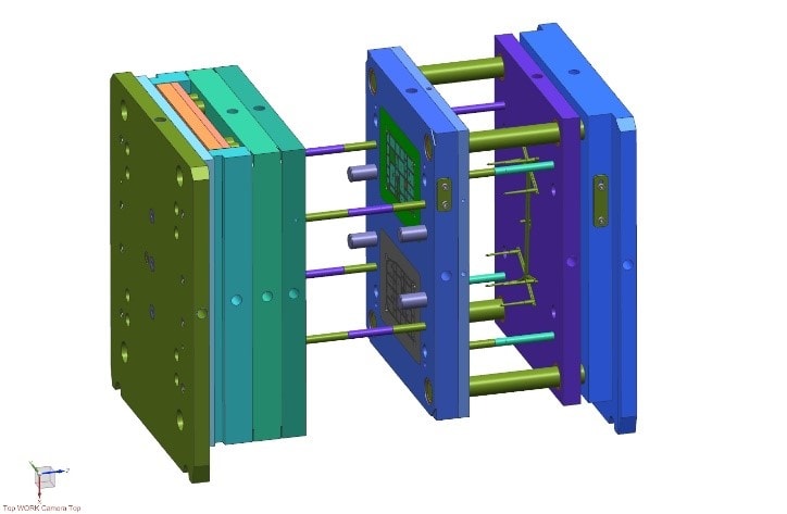
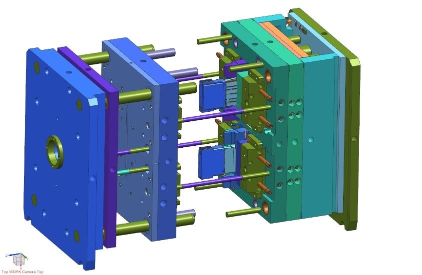
See the above example of a standard mold base for a typical round part, the bottom half is pictured on the left, and the top half is on the right. This base has 4 cavities, to mold 4 parts at a time with each cycle. A cycle consists of the time it takes to mold a part starting with the mold closing, material injecting, cooling, mold opening and part ejection.
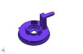
Pictured to the left is a typical round part
produced from a standard mold base.
Hot Runner Mold
A hot runner mold is similar to the traditional cold runner mold, except that it injects plastic directly into the cavity through a nozzle, as opposed to one gate location flowing through a channel into the cavities. With this design, there is no runner and therefore is no waste. A hot runner tool is costs more to construct compared to cold runner molds, but could be the economical choice if there would be a large runner created that could not be reused, or when the parts are very small especially in cases where the parts are even smaller than the runner. In that scenario, the runner would be wasting a lot of material.
A hot runner tool has more pressure and mechanics involved, especially with multi-cavity molds. This can improve the cycle time needed to mold the parts, and in high volume situations, shaving even seconds off of the cycle time can reap big benefits in profitability. Volume is one of the biggest considerations when deciding between a hot runner or cold runner tool.
Due to the mechanics and the pressure, the resin stays in a molten state until injected into the cavity. This improves consistency in molding as the material maintains a balanced melt flow with constant temperatures. This improves filling and packing in tight geometrical areas. This design also allows for flexibility with gate location. The gate can be placed in the most favorable location to achieve consistent filling and packing. This is important for surface areas with high visibility.
Two different types of gating mechanisms are available in hot runner tools. A thermal gate is commonly referred to as hot-tip gating. This is where the plastic in the nozzle solidifies at the tip, allowing the parts to cool and disconnect from the nozzle prior to ejecting. Conversely, another type is called a valve gate. This is where the material stays molten in the tip of the nozzle, but a valve slides over to seal the orifice prior to ejecting, eliminating any molten material of dropping or stringing from the nozzle tip. This is beneficial for some thermoplastic materials depending on the melt flow, as they may not solidify completely in the nozzle tip causing quality problems with molding.
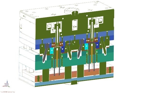
Cross section view of a hot-runner mold
Hot-to-Cold
A hot-to-cold tool is a hybrid of both a hot runner and cold runner tool. The typical hot runner tool has a nozzle for each cavity, whereas a cold runner has no nozzle, but the runner system taking plastic to each cavity. In a hot-to-cold mold, a nozzle supplies plastic to a shortened runner system taking material to possibly two cavities instead of just one. This is less expensive to construct than a full hot runner mold, but savings could be realized if the reduction in runner size is significant.
Shuttle System
So far we have discussed molds to be used in a horizontal clamping press. A shuttle system, on the other hand, are tools built to be used in a vertical clamping press. A vertical press is typically used for insert molding, also referred to as over-molding. This is where an operator would load an insert usually made of either hardened plastic or metal, into a bottom half of a mold where plastic will be molded around it. A shuttle system requires at least 2 bottom halves of the mold, one on each end of a rotary table, and one top half where the plastic injects into the mold. The operator loads an insert into the bottom half in front of them, spins the table on the press so that the A half comes down to mold plastic around the insert. While the molding is happening on the opposite side of the rotary table, the operator is removing molded parts and placing inserts into the bottom half in front of them. Shuttle systems can contain two, three or sometimes four bottom halves of a tool, depending on the press and the volume requirements. This type of molding is more labor intensive as an operator is required to load inserts unless the project is fully automated with robots.
A shuttle mold with two bottom (B) halves and one top (A) half. The operator loads and unloads inserts into the bottom of the front B side, while molding is performed in the back.
Three-Plate Tools
A three-plate mold may be necessary in designs with multiple cavities when a typical two plate cold runner mold does not allow for a suitable gate location or multiple gate locations. An additional stripper plate is added to butter between the multiple gate locations in the injecting plate, and the B plate with cavities. In this design, the runner is ejected in between the first and second plates, and the part will eject between the second and third plates, allowing for separation of parts and runner. This type of tool can be less expensive than a hot runner tool, but still allow for multiple gates providing even flow to critical dimensions of multiple cavities.
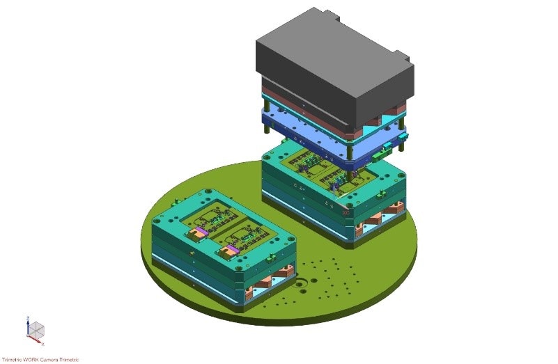
Typical Three-Plate Mold in open ejection position. Ejection of the runner is in between the two plates on the far right, ejection of parts is occurring in between the middle and far left plates.
A more complex Three-Plate mold
with cams and lifters, in open full
ejection position.
Summary
In summary, as you can see there are numerous design considerations for different molds. While there is no substitution for experience, mold builders today must utilize the new technology and computer aided simulations to produce the most appropriate tool for the project. A skilled mold builder will know just which type of tool will best suit your project needs by taking into consideration the part design and manufacturability of the geometrical tolerances involved, the environment the mold will run in and the overall functionality of the part required as derived by customer specifications.
Contact Michiana Global Mold today for full service mold building of any type of tool from prototyping only a few hundred parts to millions of parts for high volume precision components. We have the engineering technology, and the experience to build a quality mold, which is the key to quality parts.